// ————————————————————————————————————————————————
// Project: DataLogger
// Version: 0.4
// Date: 26 August 2018
// Author: Greg Howell <gjhmac@gmail.com>
// ————————————————————————————————————————————————
// Version Date Comments
// 0.4 26 August 2018 Modified code to only log to the SD card if the new value is different to the old value
// 0.3 30 June 2018 Added debugging and diagnostics on serial port, sped up ADC for analogue read (128kHz -> 1MHz), fixed “A REF”
// 0.2 26 April 2018 Addition of switch to enable/disable logging to SD card and LED to indicate logging status
// 0.1 17 February 2018 Initial Development
//
// ————————————————————————————————————————————————
// Description:
// – Logs analog0 value to a text file on the SD card along with date/time stamp in CSV format
// – Maintains date/time via DS1302 Real Time Clock
// – Builds with Arduino 1.8.5
// ————————————————————————————————————————————————
// #includes
#include <SPI.h> // Serial Peripheral Interface
#include <SD.h> // SD Cards
#include <DS1302.h> // DS1302 RTC
const int chipSelect = 4;
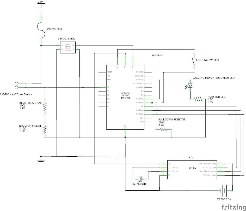
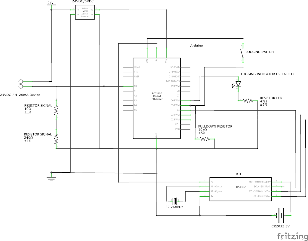
const int buttonPin = 5; // Pin 5 is the button to enable/disable logging (digital input)
const int ledPin = 6; // Pin 6 is the LED indicate logging status (digital output)
const byte PS_128 = (1 << ADPS2) | (1 << ADPS1) | (1 << ADPS0);
const byte PS_16 = (1 << ADPS2);
int buttonState = 0; // initialise button state to off
int oldsensor; // variable to store the previous sensor value (used in loop())
// Init the DS1302
// Pin 2 = RST
// Pin 3 = DAT
// Pin 4 = CLK
DS1302 rtc(2, 3, 4);
// ————————————————————————————————————————————————
// setup()
// ————————————————————————————————————————————————
void setup() {
ADCSRA &= ~PS_128; // remove prescale of 128
ADCSRA |= PS_16; // add prescale of 16 (1MHz)
analogReference(EXTERNAL); // Analogue reference set to “A REF” pin
pinMode(buttonPin, INPUT); // Initialize the pushbutton pin as an input
pinMode(ledPin, OUTPUT); // Initialize the LED pin as an output
rtc.halt(false); // Set the clock to run-mode
rtc.writeProtect(false); // and disable the write protection
Serial.begin(9600);
// Use following lines once to set clock if battery fails (modify to suit)
//rtc.setDOW(SUNDAY); // Set Day-of-Week to FRIDAY
//rtc.setTime(21, 50, 0); // Set the time to 12:00:00 (24hr format)
//rtc.setDate(26, 8, 2018); // Set the date to August 6th, 2010
while (!Serial) {
; // wait for serial port to connect. Needed for native USB port only
}
// Print current system date from RTC at start up
Serial.print(“System date: “);
Serial.println(String(rtc.getDateStr()) + “,” + String(rtc.getTimeStr()));
Serial.print(“Initializing SD card…”);
// see if the card is present and can be initialized:
if (!SD.begin(chipSelect)) {
Serial.println(“Card failed, or not present”);
// don’t do anything more:
while (1);
}
Serial.println(“card initialized.”);
}
// ————————————————————————————————————————————————
// loop()
// ————————————————————————————————————————————————
void loop() {
String dataString = “”; // make a string for assembling the data to log
int sensor = analogRead(A0); // read analogue
dataString += String(sensor); // construct string with analogue signal
buttonState = digitalRead(buttonPin); // read button state
// Logging enabled
if (buttonState == HIGH) {
File dataFile = SD.open(“datalog.txt”, FILE_WRITE);
// if the file is available, write to it
if (dataFile) {
// if the new data is different to the old data write it to file
if (sensor != oldsensor) {
// Write data to serial output
Serial.println(String(rtc.getDateStr()) + “,” + String(rtc.getTimeStr()) + “,” + dataString);
Serial.println(String(sensor) + “,” + String(oldsensor));
// Write data to SD card
dataFile.println(String(rtc.getDateStr()) + “,” + String(rtc.getTimeStr()) + “,” + dataString);
dataFile.close();
}
else {
dataFile.close();
}
// set logging LED to high
digitalWrite(ledPin, HIGH);
}
// if the file isn’t open, print an error
else {
digitalWrite(ledPin, LOW);
Serial.println(“error opening datalog.txt”);
}
}
// Logging disabled
else {
// set logging LED to low
digitalWrite(ledPin, LOW);
}
// set the old sensor value to the current sensor value (read at top of loop())
oldsensor = sensor;
// Wait before repeating 🙂
delay (500);
}
Category Archives: Computers
[Part 6] Arduino Data Logger
// ————————————————————————————————————————————————
// Project: DataLogger
// Version: 0.3
// Date: 30 June 2018
// Author: Greg Howell
// ————————————————————————————————————————————————
// Version Date Comments
// 0.3 30 June 2018 Added debugging and diagnostics on serial port, sped up ADC for analogue read (128kHz -> 1MHz), fixed “A REF”
// 0.2 26 April 2018 Addition of switch to enable/disable logging to SD card and LED to indicate logging status
// 0.1 17 February 2018 Initial Development
//
// ————————————————————————————————————————————————
// Description:
// – Logs analog0 value to a text file on the SD card along with date/time stamp in CSV format
// – Maintains date/time via DS1302 Real Time Clock
// – Builds with Arduino 1.8.5
// ————————————————————————————————————————————————
// #includes
#include
#include
#include
const int chipSelect = 4;
const int buttonPin = 5; // Pin 5 is the button to enable/disable logging (digital input)
const int ledPin = 6; // Pin 6 is the LED indicate logging status (digital output)
const byte PS_128 = (1 << ADPS2) | (1 << ADPS1) | (1 << ADPS0);
const byte PS_16 = (1 << ADPS2);
int buttonState = 0; // initialise button state to off
// Init the DS1302
// Pin 2 = RST
// Pin 3 = DAT
// Pin 4 = CLK
DS1302 rtc(2, 3, 4);
// ————————————————————————————————————————————————
// setup()
// ————————————————————————————————————————————————
void setup() {
ADCSRA &= ~PS_128; // remove prescale of 128
ADCSRA |= PS_16; // add prescale of 16 (1MHz)
analogReference(EXTERNAL); // Analogue reference set to “A REF” pin
pinMode(buttonPin, INPUT); // Initialize the pushbutton pin as an input
pinMode(ledPin, OUTPUT); // Initialize the LED pin as an output
rtc.halt(false); // Set the clock to run-mode
rtc.writeProtect(false); // and disable the write protection
Serial.begin(9600);
// Use following lines once to set clock if battery fails (modify to suit)
//rtc.setDOW(THURSDAY); // Set Day-of-Week to FRIDAY
//rtc.setTime(15, 50, 0); // Set the time to 12:00:00 (24hr format)
//rtc.setDate(26, 4, 2018); // Set the date to August 6th, 2010
while (!Serial) {
; // wait for serial port to connect. Needed for native USB port only
}
// Print current system date from RTC at start up
Serial.print(“System date: “);
Serial.println(String(rtc.getDateStr()) + “,” + String(rtc.getTimeStr()));
Serial.print(“Initializing SD card…”);
// see if the card is present and can be initialized:
if (!SD.begin(chipSelect)) {
Serial.println(“Card failed, or not present”);
// don’t do anything more:
while (1);
}
Serial.println(“card initialized.”);
}
// ————————————————————————————————————————————————
// loop()
// ————————————————————————————————————————————————
void loop() {
String dataString = “”; // make a string for assembling the data to log
int sensor = analogRead(A0); // read analogue
dataString += String(sensor); // construct string with analogue signal
buttonState = digitalRead(buttonPin); // read button state
// Logging enabled
if (buttonState == HIGH) {
File dataFile = SD.open(“datalog.txt”, FILE_WRITE);
// if the file is available, write to it:
if (dataFile) {
// Write data to serial output
Serial.println(String(rtc.getDateStr()) + “,” + String(rtc.getTimeStr()) + “,” + dataString);
// Write data to SD card
dataFile.println(String(rtc.getDateStr()) + “,” + String(rtc.getTimeStr()) + “,” + dataString);
dataFile.close();
digitalWrite(ledPin, HIGH);
}
// if the file isn’t open, pop up an error:
else {
digitalWrite(ledPin, LOW);
Serial.println(“error opening datalog.txt”);
}
}
// Logging disabled
else {
digitalWrite(ledPin, LOW);
}
// Wait before repeating 🙂
delay (200);
}
[Part 5] Arduino Data Logger
[Part 4] Arduino Data Logger
[Part 3] Arduino Data Logger
[Part 2] Arduino Data Logger
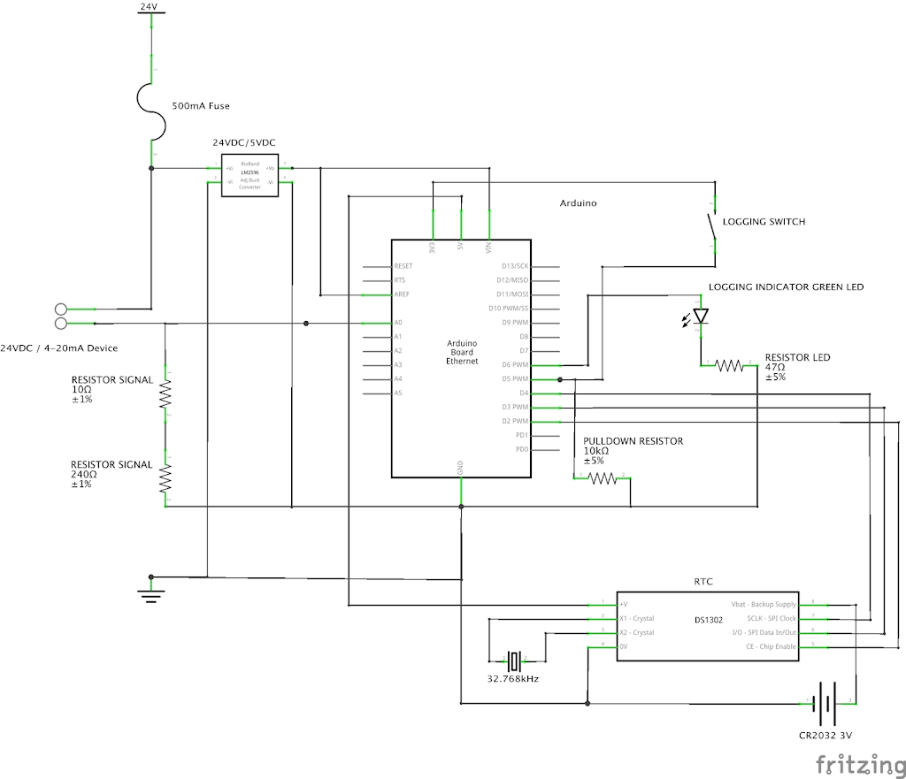
- For the external plug pack I selected the POWERTRAN MB8968B from Altronics. Input is 100-240VAC @ 50-60Hz/0.8A, output is 24VDC @ 1A.
- To produce the 5VDC (from the 24VDC) for the Arduino I selected the Z6334 DC-DC Buck Module from Altronics. Input is 3-40VDC, output 1.5-35VDC @ 3A maximum (adjusted to provide a 5VDC output).
- To maintain the date and time while the logger is powered off I selected the DS1302 based Real Time Clock Module from Altronics. Reports online indicate that the DS1302 chip can be unreliable (as opposed to the DS1307) but I have had no issues with the one I purchased.
- The Arduino I selected was one I had already, the Freetronics EtherTen. The on-board MicroSD slot was the main reason I decided to use this, I didn’t require the Ethernet port.
[Part 1] Arduino Data Logger
This is the first post in a series in which I’ll document the development of an Arduino-based data logger. The requirements for this data logger are:
- Data to be logged is a 4-20mA current loop signal (2-wire) from a sensor (using 4-20mA for analogue measurement is an industrial automation standard);
- Sensor requires a 24VDC supply (I’ll be using a 240VAC-to-24VDC transformer plug pack to provide the 24VDC so there will be no mains supply work required);
- Whole system to be contained in a box that can be sealed up and made “weather-proof”.
SM Bus Controller Driver for Lenovo ThinkPad X220i
If you are installing Windows on a Lenovo ThinkPad X220i and wondering (like me) why the Lenovo drivers don’t seem to work for the SM Bus Controller, have a look at the following link. In case you are wondering, the SM Controller is a motherboard chipset that monitors temperatures and voltages (SM = “System Management”).
Minecraft on an iMac Core 2 Duo 2.4 GHz 20-inch (Al)
Just in case anyone out there on the Internet would like to know, the current version of Minecraft runs quite happily (according to Mr 7 y.o.) on an iMac Core 2 Duo 2.4GHz 20-inch (Al). The iMac has 4GB of RAM and is running Mac OS X 10.11 “El Capitan”.
Pebble Smartwatch
I am now the proud owner of a Pebble Smartwatch (I went for the “Classic” version). It seems to play nicely with my iPhone 5s. My favourite “watchface” at the moment is the built in “time as text” one (although I do think the iWatch one is cool).
I have installed the Pebble SDK and I am going to try to develop an app/watchface or two. Stay tuned.
